PORT DOCK RAILWAY STATION
Soffit Replacement and BIM Coordination
BIM modelling, workshop drawings and architectural visualisation for a complex geometric canopy soffit.
Project Overview
Facade Drafting Solutions was engaged by Cladding and Roofing Contractors to prepare the workshop drawings for the replacement soffit cladding at Port Dock Railway Station.
The canopy combines existing structural steelwork with a highly articulated soffit comprising rectangular, triangular and custom multi-sided panels. Developing the cladding as a coordinated three-dimensional system allowed the panel geometry, joints, support angles and integrated lighting to be resolved before fabrication.
The Cladding System
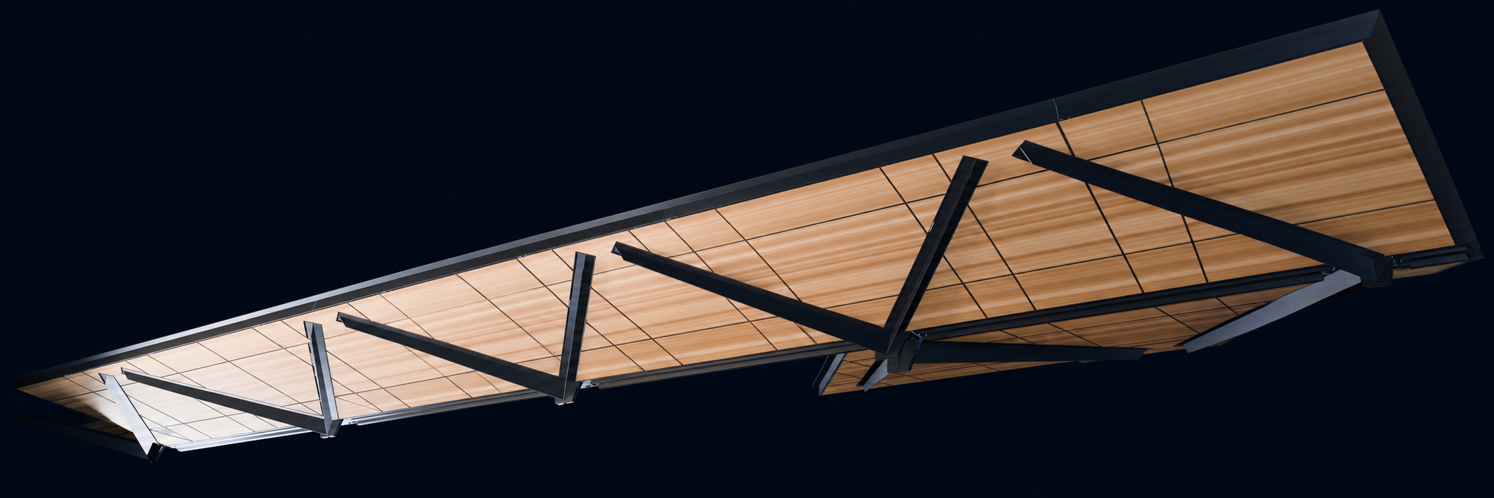
The replacement soffit was developed as a system of custom 3 mm solid aluminium cassette panels with 25 mm folded returns. The panels incorporate concealed Z-angle supports, expressed 15 mm joints and a birch-look finish that brings warmth and visual character to the underside of the steel canopy.
A combination of rectangular, triangular, parallelogram and irregular multi-sided panels was required to follow the structural geometry. The layout was also coordinated around the steel framing and continuous linear light fittings.
BIM Modelling and Workshop Drawings
A detailed BIM model was developed using parametric panel families created specifically for the project. Panel dimensions, angles, material and thickness could be adjusted independently while maintaining the cassette construction and perimeter support system.
Working in three dimensions allowed the cladding on both sides of the canopy to be positioned, mirrored and coordinated against the existing steel model. This provided a reliable basis for preparing the workshop drawings and identifying geometric or coordination issues before manufacture.
Design Visualisation
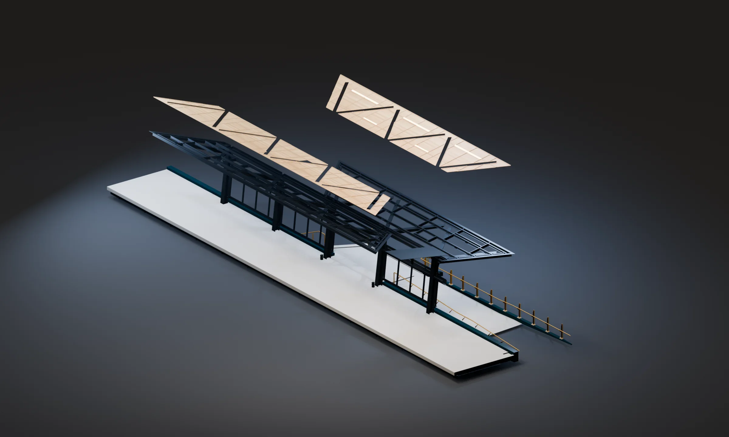
The coordinated BIM model was also used to produce realistic architectural renders and exploded assembly views.
These visualisations clearly communicate the relationship between the finished soffit panels, structural steel, support system and lighting. They provide the contractor, consultants and project stakeholders with a much clearer understanding of the proposed result than conventional two-dimensional drawings alone.
A Digital-First Delivery Process
By combining parametric BIM modelling, detailed workshop documentation and high-quality visualisation, Facade Drafting Solutions creates a clear path from design intent to fabrication.
This approach improves coordination, reduces ambiguity and gives project teams a practical tool for reviewing complex façade and cladding systems before materials reach the workshop or site.
PROJECT SERVICES
BIM Modelling · Cladding Workshop Drawings · Parametric Panel Development · Design Coordination · Architectural Visualisation